GoPro Dolly – Motor Testing from Rob Antill on Vimeo.
I’ve got a big exciting project coming up which will involve a fair amount of time-lapse bits. So to make the shots look a bit more interesting I set out to make my own motorized time-lapse dolly. The above video was shot entirely with a GoPro Hero 2 and the little rig I built.
Click below to read how it was made…
So here is a pretty brief walk through on how to make your own time-lapse motor winch box thing.
Note: This is a real budget build. I know there are many ways to build a time-lapse rig, most of which are rather complicated and requite carrying around a fair amount of gear. The idea of this one was to be able to stick it in a back-pac and take it where ever. So if you’re looking just add a bit more depth to those time-lapses this might be the solution…
The pulley needs to be going real slow. This meant trying to figure out a way to gear down a motor. Luckily I managed to find the perfect thing..
I got most of the components I needed from maplins. Which were:
- One 1.5V Motor and multispeed gear box. (Google search)
- An on/ off/ on switch (allows for two speeds. More on that later)
- A plastic enclosure (Something like this)
- Dual AA battery case
- 2 x 3A Silicon Rectifiers (Maplins 1N5401 Order Code: QL82D)
- Some thin cable (I used the cable from an old pc case fan)
- Some sort of drive wheel (I used a Lego wheel)
- Two rechargeable AA batteries (Regs ones would work to, just wanted to save on running costs)
- Drill
- Screw driver
- Cool melt gun
- Soldering iron
- Solder
- Beer
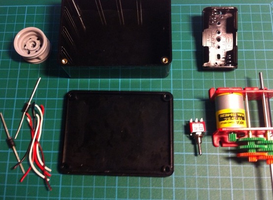
Here’s most of the parts laid out ready.
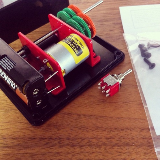
Components placed in the box to see the best arrangement for them. It looks like it will be a tight fit.
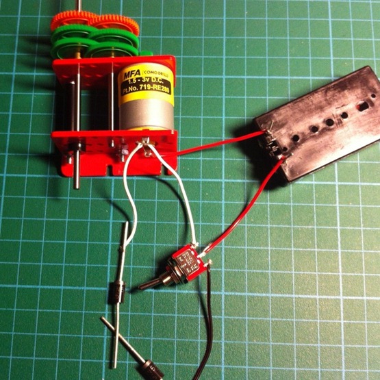
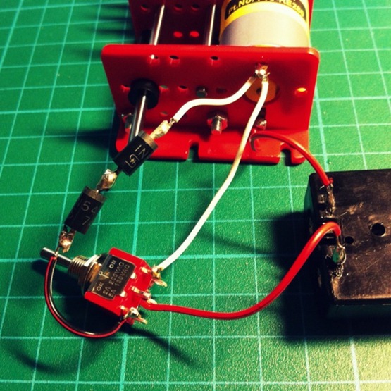
Initial circuit testing. I got a two way switch. This allows you to switch between two different circuits. One loop is direct power from the battery to the motor (full speed) and the other has two resistors that slow the current, allowing for a reduced speed.
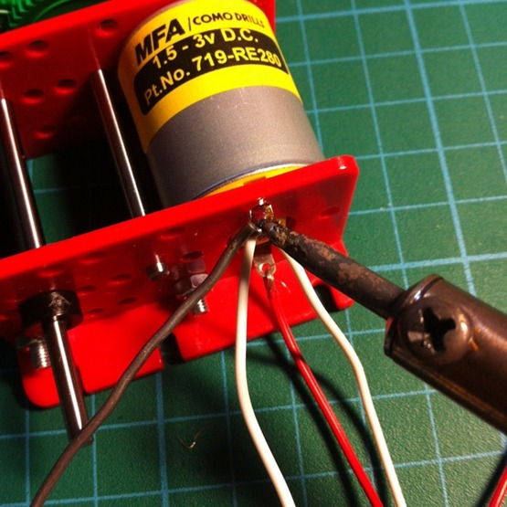
Once happy with the circuits I began soldering them in place.
It’s been a while since I last busted out the soldering iron. Not that bad of a job I would say 😐
Testing the motor still runs. Yep.
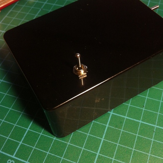
Measured out a suitable place for the switch (in this case, between the motor and the batteries). I then drilled a small hole and fastened it in.
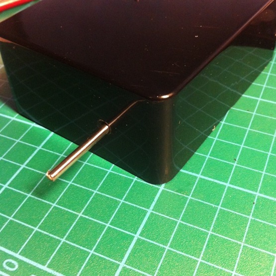
Another small hole at the front to allow the drive shaft through.
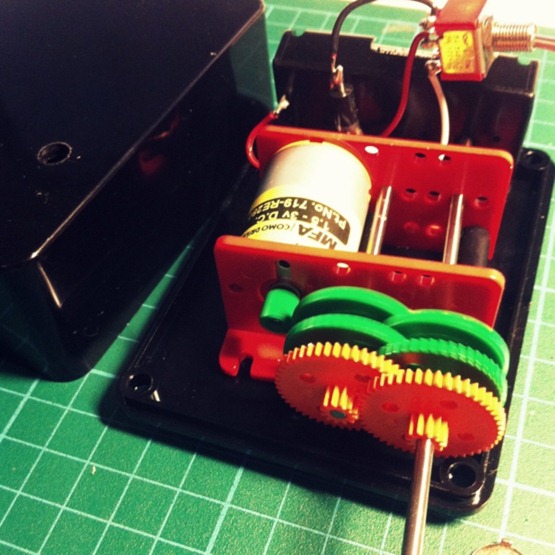
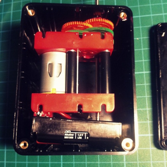
All the components in place in the box. Its was a super tight fit. Perfect fit you might say..
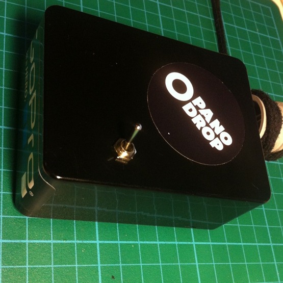
Mandatory stickers. You can also see the first test with a shoe lace attached to the sprocket. The sprocket it held in place with a generous blob of cool melt glue.
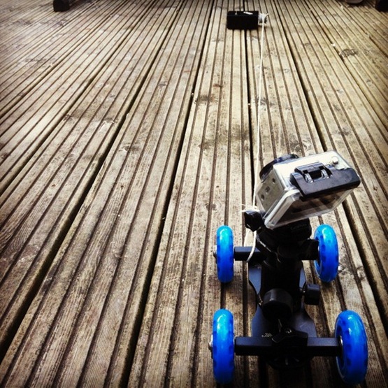
The shoe lace was far too thick. As it wound in, the sprocket got to bound up and the string just slipped off. In fact I had the same issue with the above test also. Even though the string is thinner, winching it in like this just doesn’t work. Tention builds up on the cable until the dolly shifts, usually too much, then the cable becomes slack again. This jolty motion just isn’t good enough.
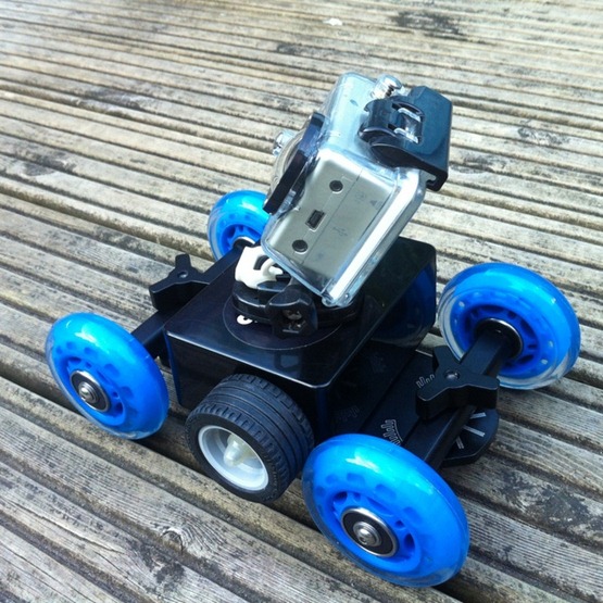
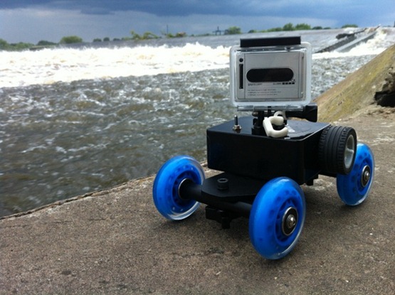
I was going to make a dolly, but in the end I decided it would be easier to just buy one of these things. They work surprisingly well. Great for DSLR video work also.
After the failed first attempt I tried driving one of the wheels directly with the motor. This method works well, except when this wheel looses traction and the whole thing stops. I think adding an elastic band or something to this wheel would provide enough height difference to keep it on the ground the whole time.
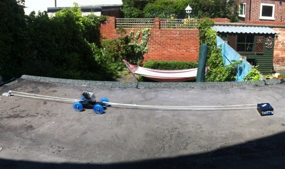
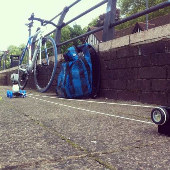
Option two for the winch method is this. Im sure it has a technical name, but basically I created a loop of string with the dolly in the middle. This meant making a little wheel at the other end. This method keeps the string taught at both ends, so the dolly travels on a smooth path.
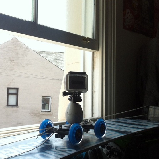
The smoother the surface the better.. Here Im using my snowboard.
Here I’ve also used the panning egg times on the dolly. This gives rotation as well as the pan.
Shot of the weir
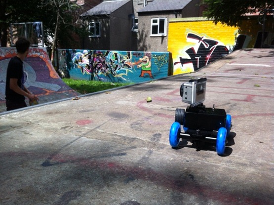
Shot of the half pipe. Maples Street Skatepark, Notts
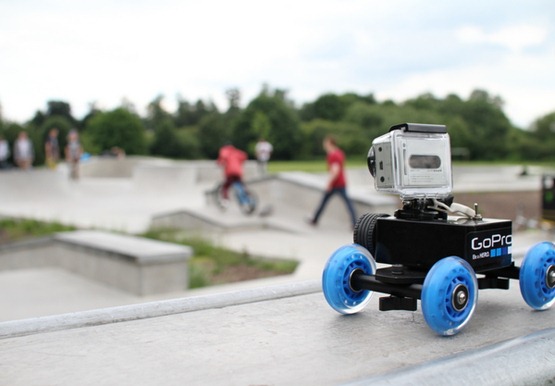
Clifton Skate Park, Notts
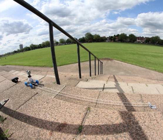
Shot under the rail. You may have noticed some jumps in the video on this section. This was due to the dolly getting caught on the gaps in the slabs.
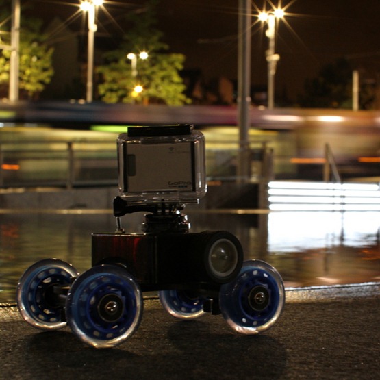
The final shots in Market Square Nottingham.
So yeah, that’s about it. If you give this project a try, it would be cool to see what you come up with. If you have any questions just give me a shout.
Follow on twitter for more current stuff..

Recent Comments